
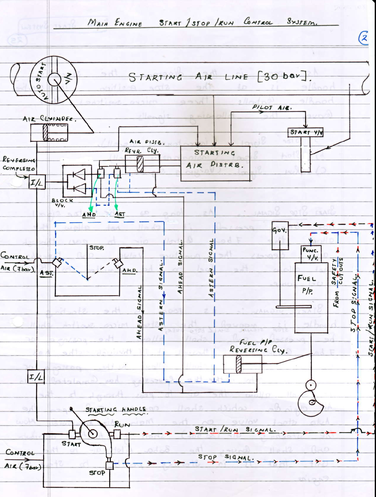
As seen in above manoeuvring diagram the starting handle is at the stop position. The starting handle control three micro switches that convey the following signals
- Stop signal (instantaneous signal)
- start signal (instantaneous signal)
- Run signal (varying signal)
Stop Signal
As long as stop signal has been pressed ,it shall allow the 7 bar control air to pass through and depress the puncture valve and their by not allow the fuel to be admitted to the fuel pump.
Start signal
As soon as the starting handle is moved,the start micro switch will be pressed and stop signal will be over which allows the passage of 7 bar control air through it.If no interlock has operated then it shall allow further passage of the air .Now if the reversing is completed then it shall allow the air to pass through to the air cylinder which shall operate and open the auto start valve on the main air manifold,now the starting air (30 bar) shall go to the distributor and shall convey the 30 bar pilot air to the unit which is in the starting position to start the engine.
Run Signal
Once the engine has started we shall further press the starting handle to the run position and the start signal finishes.The run micro switch being of varying type ,more the handle is turned ,more the switch would be compressed and the output of it shall vary accordingly . The varying signal control the 7 bar control air output that is fed to the governor to increase the fuel proportionately.
Reversing
The engine has stopped in the Astern position and we shall want to move in ahead position, so we will put the AHD/AST Lever to the ahead position , allowing the 7 bar control air to pass through (the pressed AHD micro switch ) and go to
- the fuel pump to reverse the cam position via the reversing cylinder
- to the starting air distributor reversing cylinder to reverse the distributor
Reversing Completed Interlock
As the reversing has completed ,the shaft of the start air distributor reversing cylinder shall move outwards to press the AHD micro switch ,allowing a part of (7 bar) control air to pass through it and a block valve is released and fulfill the reversing completed interlock.This is provided so that in the event of the reversing cylinder being stuck between AHD/AST micro switch ,then in that condition the interlock shall not allow the auto start valve to open.
when start command is given, the stop command is still active and not over. otherwise the AIR/FUEL interlock will operate.
At start signal,stop signal is getting deactivated as the cam is no longer touching the stop micro switch and puncher valve of fuel pump is depressurised and so engine can start.
What you are saying will cause the air and fuel to introduce in the cylinder at the same time. How it can be possible?
In the above description its mentioned that run signal is of varying type‚ more the handle is turned ‚more the switch would be compressed and the output of it shall vary accordingly, so initially the governor rack is at zero position when start signal is pressed no fuel is introduced during start signal . when the rpm picks up the handle is further moved which ends the start signal thereby stops the 7 bar air to the air cylinder and distributor(cutting off starting air ) further it compresses the run signal initiating governor rack to increase fuel which starts the engine.Thus avoiding air and fuel to introduce in the cylinders at the same time.