SAFETY VALVES
At least two safety valves have to be fitted to the boiler. They may be both mounted on a common manifold with a single connection to the boiler. The safety valve size must not be less than 38mm in diameter and the area of the valve can be calculated from the following formula
C x A x P = 9.81 x H x E
where
H= Total heating surface in m3
E = Evaporative rate in Kg steam per m2 of heating surface per hour
P = Working pressure of safety valves in MN/m2 absolute
A = Aggregate area through the seating of the valves in mm2
C = the discharge coefficient whose value depends upon the type of valve.
C=4.8 for ordinary spring loaded valves
C=7.2 for high lift spring loaded valves
C= 9.6 for improved high lift spring loaded valves
C= 19.2 for full lift safety valves
C= 30 for full bore relay operated safety valves
LIFT PRESSURE
The safety v/v must be set at a pressure not exceeding 3% of the approved boiler working pressure. It is normal to set the suphtr safety below that of the drum to ensure an adequate flow of stm for cooling purposes under fault conditions. Similarly the superheater should be set to close last.
10% ACCUMULATION OF PRESSURE RULE.
With all the flames in full firing the stm stop is closed, the boiler pressure must not increase by more than 10% in 7 minutes for water tube of 15 mins for tank boilers with the safety lifted. this is normally waivered for superheater boilers. Instead calculations and previous experience used.
BLOWDOWN
The pressure drop below the lifting pressure for a safety v/v is set at 5% by regulation although it is more normal to set v/v’s at 3% to prevent excessive loss of stm. For boilers with a superheater it is important that the superheater v/v not only lifts first but closes last.Adjustement of the blowdown may be necessary following adjustment of the popping setpoint (Increaseing set point lengthens blowdown). Adjustment is achieved by altering the height of the ‘adjusting guide ring’ on the full lift safety valve design shown below. Over raise adjustment of this ring can lead to mal-operation with the valve not fully opening
SETTING
Must be set with the surveyor present except when on the waste heat unit. A chief engineer with three years experience may then set the safety valve but must submit information to surveyor for issue of certificate.
Superheated steam safety valves should be set as close to operating temperature as possible as expansion can alter the relationships between valve trim and guide/nozzle rings which can effect the correct operation of the valve.
- Two safety valves- each set independently
- Each safety valve must release entire steam flow in pressure accumulation test
- Surveyor uses specially checked gauge
- One valve gagged
- valve initially set to approximately the correct position then steam pressure increased to set pressure
- adjust valve to lift
- raise and lower pressure to check
- fit locks to both valves on completion
Easing gear to be checked free before setting valves. Steam should not be released as this can damage seat.
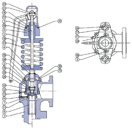
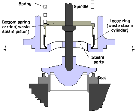
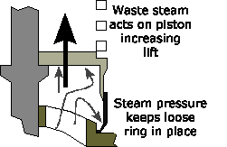
Improved high lift safety valve
Differences in the ordinary and high lift designs
| Ordinary | High Lift | Improved High Lift |
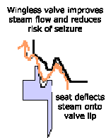
| Winged valve | Winged valve | Wingless valve |
| No waste piston | Waste piston | Waste piston |
| No floating ring | Floating ring |
For superheated steam the aggregate area through the seating of the valves is increased, the formula is
As = A(1 + Ts/555)
where
As = Aggregate area through the seating of the valves in mm2 for superheated steam
A = Aggregate area through the seating of the valves in mm2 for sat steam
Ts = degrees of superheat in oC
As is greater than A due to the higher specific volume of superheated steam requiring more escape area.
The manifold pipe must have an area equal to at least Н of A, the exhaust must have a diameter dependent on the type of valve but up to 3 x A for a full bore relay operated valve.
A drain pipe must be fitted to the lowest part of the valve, it should have no valve or cock and should be checked clear on regular occasions.
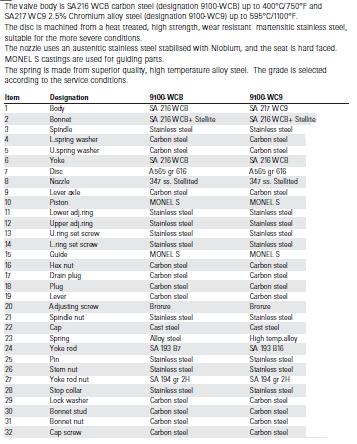
Materials
Materials for all parts must be non corrodible. Common materials are Bronze, Stainless steel or Monel metal, depending on the conditions of service. The valve chest is normally made of cast steel.
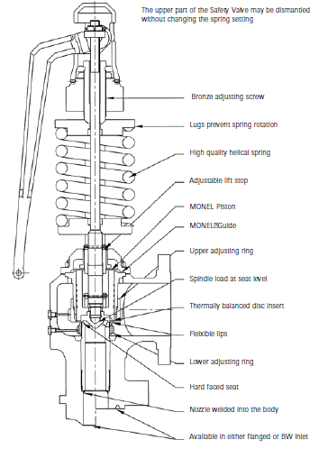
Full lift safety valve
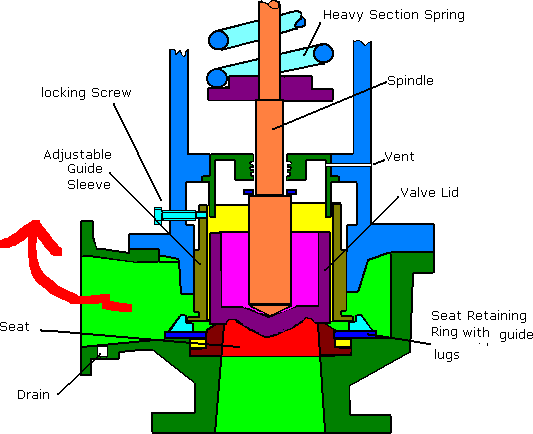
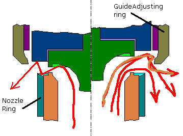
This is a modern version of the high lift safety valve incorporating the piston and reaction force effects to improve valve lift. In addition the inlet pipe is tapered to give a nozzle effect increasing the reaction on the lid.
The initial lift is produced when the steam pressure under the disc exceeds the spring pressure. As the valve begins to open a thin jet of steam escapes and is deflected by a small angle on the nozzle ring. As the lift increase the steam begins to react against upper guide ring increasing to ‘full bore’lift. Full Bore lift is defined as that point where the area of the nozzle, rather than the lift, limits the discharge capacity of the valve. The form of the valve offers an increased area to the steam jet stream and the design allows for a piston effect of the valve trim assembly as it enters in the guide ring cylinder, both these effects increase lift and improve action of the valve
The guide sleeve is adjustable allowing alteration of the blowdown.
With boiler pressure dropping the valve begins to close. When the lid just exits the guide sleeve there is a loss of the reaction and piston effect and the valve tends to snap shut cleanly.
Blowdown adjustment is achieved by altering the height of the adjusting Guide Ring. On some designs a second adjustable ring is mounted on the nozzle, this allows adjustment of the ‘warn’ or ‘simmering’period and increases the popping power. Adjustment of this ring is critical to operation, after factory setting it is generally unnecessary and no attempt should be made to remove slight ‘warn’
Full lift safety valve
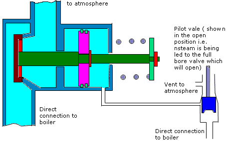
Seen fitted to large high pressure boilers
This design offers sveral advantages over simple high lift valves
- Complicated design to achieve high lift is obviated
- Pilot valve may be mounted on the drum and the main valve maounted on the superheater thus making the system more sensitive to load changes (over pressurisation will first be seen in the steam drum before the superheater. In addition the pilot valve and main valve piston arrangements are subject to lower steam temperatures
- Boiler pressure will assist to close the main valve rapidly leading to very small blowdown
Easing gear
This is fitted to safety valves to allow manual operation of the valve in an emergency.
Steam valve and material