The Crankshaft And Its Types
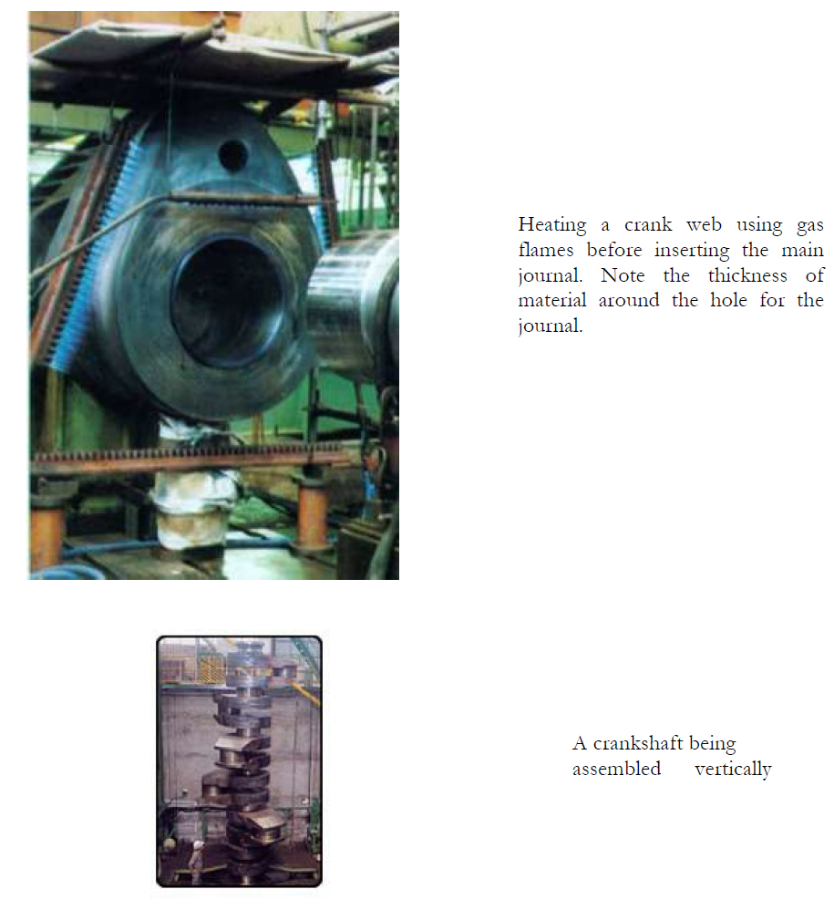
The crankshafts on the large modern 2 stroke crosshead engines can weigh over 300 tonnes. They are too big to make as a single unit and so are constructed by joining together individual forgings. On older engines the so called fully built method was used. This consisted of forging separate webs, crankpins and main journals. The crankpins and journals were machined and matching holes bored in the webs, which were slightly smaller in diameter. The webs were heated up and the crankpins and journals fitted into the holes (which due to the heat had expanded in size). As the webs cooled down, so the diameter of the bored holes would try and shrink back to their original size. In doing so, the crankpins and journals would be gripped tightly enough to stop them being able to slip when the engine was being operated normally. This method of construction had its origins in the days of early reciprocating steam engine crankshaft manufacture, when as well as shrink fitting, dowel pins were used (mainly because the tightness of the shrink fit could not be guaranteed). THIS FITTING OF DOWEL PINS IS NEVER USED IN THE CONSTRUCTION OF DIESEL ENGINE CRANKSHAFTS. It would act as a stress raising point from which a crack could start.
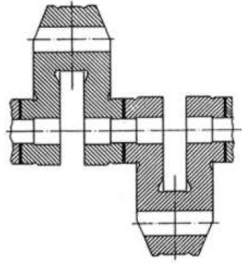
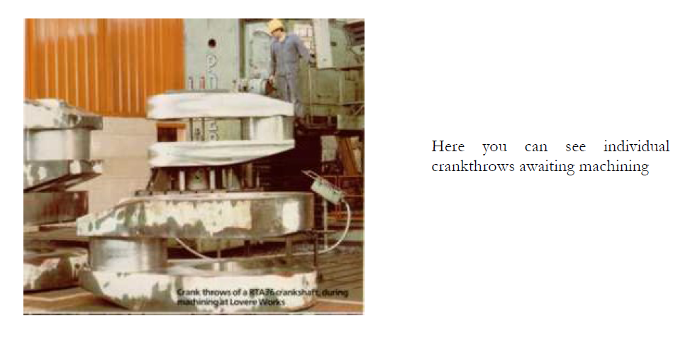
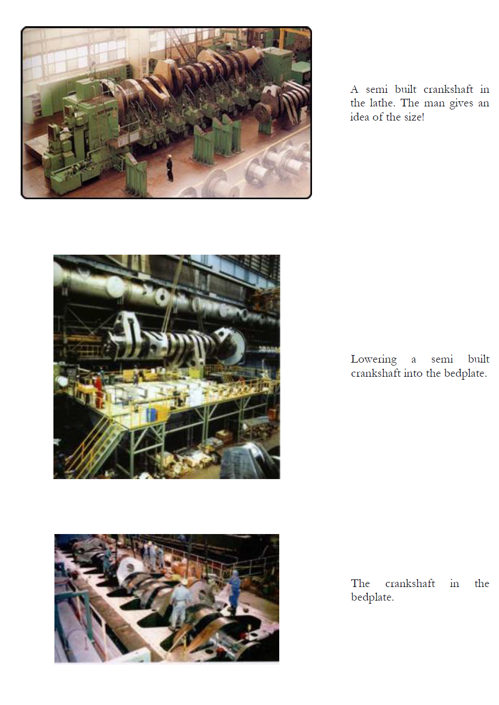
Today, crankshafts for large 2 stroke crosshead engines are of the semi built type. In this method of construction the crankshaft “throws” consisting of two webs and the crankpin are made from a single forging of a 0.4% carbon steel. The webs are bored to take the separately forged and machined main journals which are fitted into the webs using the shrink fitting method described above. The shrink fit allowance is between 1/570 and 1/660 of the diameter.
The advantages of this method of construction is that by making the two webs and crankpin from a single forging the grain flow in the steel follows the web round into the crankpin and back down the other web.
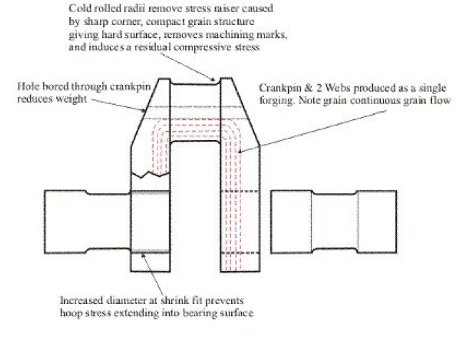
Because the crankpin and webs are a single forging, the webs can be reduced in thickness and a hole is sometimes bored through the crankpin as shown, reducing the weight without compromising strength. Note however, there is a need for a good deal of material around the holes bored to take the main journals. This is because of the large tensile hoop stress present in the material after shrink fitting. This could lead to a crack in the web if the thickness here is not adequate or if the shrink fit is too tight or if there is a flaw in the material.
The welded crankshaft
The welded crankshaft was developed in the 1980s. It was made up of a series of forgings each comprising of half a main journal, web, crankpin, second web, and half a main journal. These forgings were then welded together using a submerged arc welding process to form the crankshaft. After welding the journals were stress relieved and machined. As well as having the advantage of continuous grain flow, the webs could be made thinner (no shrink fit to accommodate), leading to a lighter shorter crankshaft.
Why aren’t all crankshafts produced by this method? Cost! It was very expensive and only about twenty crankshafts were produced by this method. They have performed very well in service however.